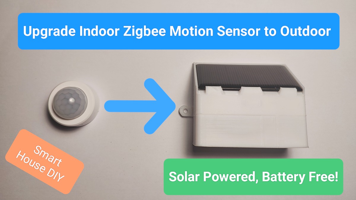
Upgrade an indoor Zigbee motion sensor for outdoor use with a solar-powered supercapacitor and 3D-printed case. No more batteries, just reliable security!
About Zigbee Motion Sensors
If you’re reading this article, chances are you either already own a couple of affordable Zigbee motion sensors from AliExpress or have seen them on sale for just a few dollars or euros. I personally use two of the most popular and budget-friendly models compatible with Home Assistant:

ZP01 model runs on two AAA batteries, while IH012-RT01 uses a single CR2450 coin cell. There is also a very similar Tuya ZG-204ZL model available to buy, it has a Luminance sensor additionally. The devices are designed strictly for indoor use and lack any moisture protection.
The Idea
Imagine living in a private house. You might have a standard security system with vibration sensors on windows and doors, or maybe no security system at all because you’re unwilling to pay for an expensive subscription. Traditional security systems typically react after a window is broken or a door is forced open — which might already be too late. Preventing a break-in before it happens is much better.

So how can we improve home security on a budget? Here’s an effective and inexpensive approach:
- Strategic Placement: Install a discreet motion sensor above each window or door, approximately 3–4 meters off the ground, and angle it directly downward to cover just the area near the window or door. Positioned this way, the sensor will be hard to notice and impossible to tamper with without a ladder.
- Smart Automation: Set up automation rules in Home Assistant (or Smart Things, Tuya app, etc.). For example:
- If motion is detected near a window or door at night or when you’re away, automatically turn on a smart device inside your home — lights, a radio, or even a TV to create noise.
- Trigger several devices sequentially at intervals.
- Send a notification to your phone.
The possible automation scenarios are endless. And what’s the likely reaction of an intruder? They’ll assume someone is home and will think twice before proceeding. Your window or door stays intact, and your home remains secure.
Implementation
Option 1: Buying Commercial Outdoor Sensors
You could simply buy outdoor-rated motion sensors. Initially, I considered this route, but after reviewing the available options, I noticed several drawbacks:
- Cost: Outdoor sensors are relatively expensive, and you’ll likely need one per door/window (e.g., five sensors for two windows on each side and a door).
- Power Supply: Most outdoor sensors require either wired power or periodic battery replacement. Given their installation height (typically out of easy reach), changing batteries regularly is highly inconvenient — even if they last 1–2 years. Managing multiple sensors exacerbates this issue. Wiring them would be even more cumbersome.
- Visibility: Factory-made outdoor sensors are often bulky and easily recognizable. Experienced burglars might spot them, deduce the automation is triggered, and realize no one is actually home.
Option 2: Upgrading Indoor Sensors for Outdoor Use
Instead of buying expensive outdoor sensors, we can upgrade affordable indoor models:
- 3D-Printed Weatherproof Enclosure: Design and print an outdoor-rated enclosure using a 3D printer. Match the enclosure color to your house walls to make it less noticeable.
- Battery-Free Power Supply: Zigbee sensors are incredibly energy-efficient, drawing only about 15µA of current when idle. This allows us to eliminate the battery entirely and instead use a supercapacitor charged by a small solar panel. I’ve previously tested this power method on other sensors and micro-controllers (like the ESP32) with excellent results. I’ll discuss the benefits of this approach in more detail later.
As you’ve probably guessed, I chose Option 2. Its implementation turned out to be both successful and quite fascinating, which is why I decided to share it in this blog. I’m sure there will be enthusiasts who’ll want to replicate this project, and a ready-made guide will make that task much easier.
I’ll share my design for a weatherproof enclosure that’s easy to print on a 3D printer. I’ll explain how I assembled the supercapacitor-based power supply, how it works, and explore simplified versions and alternative components you might already have on hand to minimize costs.
Choosing the Zigbee Motion Sensor to use
After carefully comparing and testing the two sensors I mentioned at the beginning of the article, I decided to use the IH012-RT01. Here’s why:
- Higher Sensitivity: Thanks to its larger lens, the IH012-RT01 proved to be more sensitive than the Tuya ZP01.
- Adjustable Settings: It offers more customization options, including sensitivity and keep_time, which are not available on the ZP01.
- Compact Design: The PCB of the IH012-RT01 is significantly smaller, which allows for a more compact enclosure.
Outdoor Enclosure Design
I used Tinkercad to design the 3D model of the enclosure. It consists of two parts that snap together securely.

- Top Section: Includes a slot for a small 5V solar panel. I used a 68×37mm panel that I already had on hand (I’ll provide links to all components at the end of the article for your convenience).
- Bottom Section: Holds the motion sensor PCB with lens.
- Material Choice: I printed the enclosure using PETG filament, which offers good resistance to outdoor conditions. ABS is also a viable option, but PLA should be avoided as it degrades quickly in outdoor environments.
- Print Settings:
- Supports: Disabled (not needed)
- Infill: 100%
- Adhesion Type: Brim (8mm)
- Other Parameters: Customize as needed
Choosing the Power Supply
As mentioned earlier, I wanted to eliminate the need for disposable batteries that require periodic replacement (even if infrequently).
Why Not Use a Li-ion Battery?
A small Li-ion battery charged by a solar panel was another option I considered, but it came with significant drawbacks:
- Temperature Sensitivity: Li-ion batteries are highly sensitive to temperature fluctuations. In winter, sub-zero temperatures can damage them, while in summer, a sealed enclosure exposed to direct sunlight can overheat them — significantly reducing lifespan or even causing thermal runaway (fire risk).
- Charging Requirements: Li-ion batteries require a stable minimum current for proper charging. A small solar panel might not always meet this requirement, especially in cloudy conditions.
- Complex Charging Circuit: Li-ion batteries need a dedicated charging controller, adding complexity and cost.
Advantages of Using a Supercapacitor
Switching to a supercapacitor proved to be a much better choice for this project. Here’s why:

- Minimal Power Requirements:
- A supercapacitor can charge effectively even with very low current from a small solar panel.
- Direct sunlight isn’t necessary; even under cloudy skies, the panel generates enough energy.
- For example, my 68×37mm solar panel can produce around 1-2mA on a completely overcast winter day in Ireland, which is more than enough to keep the sensor running (it consumes only about 15µA).
- Longevity:
- Supercapacitors have an extremely long lifespan compared to batteries.
- They don’t suffer from significant degradation over time.
- Temperature Tolerance:
- Supercapacitors are much more resistant to temperature extremes.
- The risk of fire or catastrophic failure is much lower compared to Li-ion batteries.
- Simplified Charging Circuit:
- There’s no need for a complex charging controller.
- A simple diode can be used between the solar panel and the supercapacitor to prevent reverse current.
- Balance circuits may be necessary if multiple supercapacitors are connected in series.
- Eco-Friendly:
- Unlike Li-ion batteries, supercapacitors don’t contain hazardous chemicals, making them more environmentally friendly.
You’re probably wondering how long a supercapacitor can power our motion sensor in complete darkness without any recharging from the solar panel.

I used two 2.7V supercapacitors connected in series with a capacitance of 10F. Here’s how I tested them:
- Initial Charge: I charged the capacitors to a combined voltage of 5V.
- Test Environment: I placed the motion sensor in a bathroom — an area visited approximately 20–30 times per day. Each visit triggered the sensor, activating it and transmitting data to the Zigbee network.
- Test Duration: The sensor operated for over one week on a single charge.
- Cutoff Voltage: The sensor stopped functioning when the voltage dropped to around 1.7V.
Pretty impressive, right?
I’m confident that you can safely use supercapacitors starting from 4F or higher. There’s really no upper limit, but going above 20F might be overkill for this application, as the diminishing returns wouldn’t justify the increased cost.
The Power Circuit
Let’s break down the power circuit based on supercapacitors and the additional components needed for stable operation.

SC1, SC2 – Supercapacitors
- Type: Two supercapacitors rated at 2.7V, 10F each.
- Reasoning: This is one of the most cost-effective and widely available options.
When connected in series, they provide a combined maximum voltage of 5.4V (2.7V × 2).
D1 – Schottky Diode
- Purpose: Prevent reverse current flow from the supercapacitors back into the solar panel when it’s not generating power (e.g., at night).
- Recommended Diodes:
- 1N5817, 1N5818, or 1N5819 (I used these because they were on hand).
- Alternatively, BAT60A or BAT54 offer slightly better characteristics, particularly lower forward voltage drop and reverse leakage current.
Why Schottky Diode?
Schottky diodes have a low forward voltage drop (~0.2–0.3V) and minimal leakage current, making them ideal for low-power solar applications.
U1, U2 – Shunt Voltage Regulators
- Type: TL431 adjustable shunt regulators.
- Purpose: To balance the charge across two supercapacitors and prevent overcharging.
How It Works:
- When the reference pin of the TL431 detects 2.5V, it opens and diverts excess voltage through R1 or R2.
- This ensures each capacitor doesn’t exceed 2.5V, preventing imbalance between the capacitors during charging.
Why not use a 2.5V Zener Diode for balancing voltage?
While you can use a 2.5V Zener diode, it’s generally less efficient than the TL431 in this application. Zener diodes typically exhibit higher leakage currents, especially when operating near their breakdown voltage. This increased leakage results in higher standby power consumption, making them less suitable for low-power setups like our supercapacitor-powered Zigbee motion sensor.
Why Not Charge to 2.7V?
- Charging supercapacitors close to their maximum rated voltage (2.7V) accelerates self-discharge and can reduce their lifespan.
- The voltage drop from 2.7V to 2.5V happens very quickly (less than an hour), so charging to 2.7V offers no significant long-term energy benefit.
- Adding voltage dividers to adjust the TL431 reference to 2.7V would also introduce additional current draw, further reducing efficiency.
Best Practice: Stick to 2.5V per capacitor for optimal performance, circuit simplicity and longevity.

R1, R2 – Resistors
- Value: 10–50Ω
- Purpose: These are optional, but they help protect the TL431 regulators in specific edge cases.
Why Use Them?
- If you initially charge the capacitors from an external power supply (e.g., to pre-charge them before installation), one capacitor might charge faster than the other.
- In such a scenario, the TL431 might activate and create a short circuit, potentially exceeding its maximum current rating (~250mA).
Are They Necessary?
- For solar panel charging, the current will always be low (in the µA–mA range), so the resistors are not strictly necessary.
- However, they act as an extra safety buffer, so if you have them, use them.
V1 – Linear Voltage Regulator (LDO)
- Purpose: Step down the variable voltage from the supercapacitors (up to 5V) to a stable 3V suitable for the Zigbee motion sensor.
- Recommended Regulators:
- XC6206P302PR (typical quiescent current: 1.0 µA) – highly efficient but comes in SMD packages (SOT-89 or SOT-23), which can be challenging to solder manually.
- MCP1700-3001E or MCP1700-3002E (typical quiescent current: 1.6 µA) – available in a TO-92 package, which is easier for manual soldering.
Why Low Quiescent Current?
- LDOs consume a small amount of current even when idle.
- Choosing an LDO with ultra-low quiescent current minimizes unnecessary power loss from the supercapacitors.
C1, C2 – Ceramic Capacitors
- Type: Ceramic capacitors.
- Value: At least 1µF on both the input and output of the LDO regulator.
- Purpose: Stabilize the voltage and filter out any noise or fluctuations.
Circuit Overview Summary:
- Solar Panel → Diode (D1) → Supercapacitors (SC1, SC2, balanced via TL431 and R1, R2) → LDO (V1) → Zigbee Sensor
- Charge Balancing: TL431 + Resistors (R1, R2)
- Voltage Regulation: LDO (e.g., XC6206 or MCP1700)
What Can Be Simplified or Improved?
Use a Single 5.5V Supercapacitor
On platforms like AliExpress, you can find 5.5V-rated supercapacitors. By using one of these, you could replace two 2.7V capacitors with a single unit, eliminating the need for:

- Balancing Circuit (U1, U2)
- Resistors (R1, R2)
Advantages:
- Simpler circuit design
- Fewer components
- Reduced complexity
Concerns:
- Many 5.5V supercapacitors are internally built from two series-connected cells. It’s unclear whether they include an internal balancing circuit, and even if they do, the leakage current characteristics are unknown.
- Without detailed specifications or real-world testing, it’s hard to predict their reliability and performance over time.
Open Question:
If anyone has experience with such 5.5V supercapacitors, especially regarding their leakage current and stability, feel free to share your insights in the comments.
Use 3.8V Supercapacitors and Charge Them to Higher Voltages
There are slightly more expensive 3.8V single-cell supercapacitors available. Charging them to a higher voltage could potentially increase energy storage efficiency.

When Does This Make Sense?
- If your solar panel consistently outputs more than 6V (which is possible with 5v panel in direct sunlight).
How to Adjust the TL431 for Higher Voltage Regulation?
- The most common approach is to use a voltage divider with two resistors to adjust the reference voltage of TL431.
- Problem: A voltage divider introduces constant current consumption, reducing overall efficiency.
Alternative Approach Using a Diode:
Instead of a voltage divider, you can use a diode with a known forward voltage drop (e.g., 0.8V).
- Connect the reference pin of the TL431 to the positive terminal of the supercapacitor through this diode.
- The diode’s forward voltage drop will effectively shift the TL431 reference by 0.8V.
Example Calculation:
- Standard TL431 reference voltage: 2.5V
- Add diode forward drop: 2.5V + 0.8V = 3.3V
- For two supercapacitors: 3.3V × 2 = 6.6V
This method is simple and avoids the constant current draw of a voltage divider.
Is it Worth It?
Realistically, this is more of an academic optimization rather than a practical one.
- Will your Zigbee sensor run for 1.5 weeks in darkness instead of 1 week? Probably yes.
- Is this improvement significant for real-world usage? Probably not.
In most cases, the solar panel will recharge the capacitors daily, making extreme optimizations unnecessary.
Conclusion:
- 5.5V Supercapacitor: A promising simplification, but needs further verification regarding internal balancing and leakage current.
- 3.8V Supercapacitors with Voltage Adjustment: Technically possible but likely unnecessary for practical usage.
If you’re aiming for maximum simplicity and reliability, stick with the current design using two well-balanced 2.7V capacitors. If you’re experimenting for fun or efficiency gains, both approaches are worth exploring!
Device Assembly
Disassembling and Preparing the Motion Sensor
- Use a small flat screwdriver to carefully extract the sensor’s PCB with the lens from its original housing.
- Gently press on the lens while using the screwdriver to release the internal latches. The PCB will come out attached to the lens.
- You’ve probably noticed an LED blinking under the lens every time the motion sensor is triggered. To make the sensor less conspicuous, I simply covered the LED with black electrical tape.
- Solder the Power Wires: Carefully solder the power wires with a connector (e.g., JST) to the sensor’s battery terminals. Double-Check Polarity: Ensure the correct polarity of the wires (+ to +, – to –) before soldering.


Assembling the Power Supply Board
- For the power supply circuit, I used a small piece of PCB Prototype Board (7×8 holes).
- If you’re using an SMD voltage regulator (LDO), solder it first for convenience. I used an SOT-89 package regulator. Here’s how I soldered it:
- Central Pin: Removed it, as it’s typically connected to the backplane.
- Left Pins (Ground and Output): Soldered them to adjacent holes on the left side of the PCB.
- Right Pin (Input): Soldered it to a hole on the right side of the PCB.
- Using the component leads, I then connected and soldered the necessary circuits on the back side of the board according to the schematic diagram provided earlier.


Enclosure Assembly
The enclosure is 3D-printed in two separate parts sequentially. Before final assembly, test snapping the top and bottom parts of the enclosure together. If they fit too tightly, carefully sand the outer edge of the bottom part and the inner edge of the top part using fine-grit sandpaper. Sand evenly around the perimeter to ensure a smooth and secure fit.


- Top Part (Solar Panel Slot):
- Insert the solar panel with pre-soldered wires and a connector (e.g., JST).
- If your panel has sharp corners on one side and rounded corners on the other, insert it with the sharp corners facing the bottom slot and the rounded corners facing the top slot.
- Pay special attention to sealing the wire hole for the solar panel. This is the most critical point for waterproofing. I applied adhesive glue (e.g., UHU All Purpose Adhesive Glue) around the wire hole and at each corner of the panel. Avoid using corrosive glues like super glue, as they may damage the plastic enclosure or the solar panel.
- The panel is inserted bottom side first, followed by the top side.
- Bottom Part (Sensor Lens Slot):
- The bottom part includes a hole for the motion sensor lens. Insert the lens and PCB from the inside.
- Ideally, sand the inner surface of the hole with fine sandpaper to ensure a snug fit with the lens.
- For additional waterproofing, you can apply adhesive glue around the lens, though this step is optional.
- To insert the sensor PCB with the lens, gently spread the enclosure walls with your fingers and slide the PCB into place. It will securely lock into the slots on both sides of the housing.


Connecting the Solar Panel and Motion Sensor to the Power Supply Board
- Once both parts of the enclosure are assembled, connect the solar panel and the motion sensor PCB to the power supply board with the supercapacitors (pre-charged).
(⚠️ Important Warning: If you accidentally reverse the polarity, the supercapacitors can deliver extremely high current, which may permanently damage the sensor if it lacks built-in polarity protection (I haven’t tested this myself). Take your time, double-check your connections, and only proceed when you’re absolutely sure the polarity is correct). - Ensure that the sensor PCB is well-insulated from the power supply PCB to prevent any short circuits. You can use a piece of thick packaging film or similar non-conductive material as an insulator.
- You can secure the power supply PCB to the top section of the enclosure using hot glue. This will keep the board in place and prevent movement during installation or operation.
- Initialize the Sensor: Pair the motion sensor with your smart home system (Home Assistant, SmartThings, Tuya app, etc.) if it wasn’t done before.
- Snap the top and bottom parts of the enclosure together.
Pre-Installation Preparation
Before mounting the sensor outdoors use an external 5V power supply to pre-charge the supercapacitors.
⚠️ Important Notes:
- Avoid letting the voltage on the supercapacitors drop below ~2V.
- If the voltage drops too low, the Zigbee sensor may enter an undefined state, where it could fail to boot even when the capacitors are slowly recharged by the solar panel.
- To recover from this state, you would need to disconnect the sensor from the power supply and then reconnect it after the capacitors have sufficient charge.
- For this reason, do not connect the sensor to fully discharged capacitors and expect it to boot properly as the solar panel gradually charges them from 0V to 2-3V.
Your sensor is now prepped, powered, and ready for outdoor installation. By ensuring the capacitors are pre-charged and the sensor is initialized beforehand, you’ll avoid common startup issues and guarantee smooth operation.
Components used (AliExpress affiliate links):
- Water resistant enclosure 3D printer model: Tinkercad, Thingiverse
- Indoor Zigbee Motion Sensor (Link1, Link2), 2 in 1 with lux (link1, link2)
- Solar panel (can be replaced with any other 5-6v panel of smaller size but you might need to edit the enclosure 3D model for better fitting)
- Super capacitors: 2.7v, 3.8v, 5.5v
- TL431 Shunt Voltage Regulators
- LDOs: XC6206P302PR (Link1, Link2), MCP1702-3002E
- PCB Prototype Boards
- Connectors and wires
Stay Updated
If you enjoyed this project and guide, follow me on social media (links in the website footer) to show your support and stay updated on similar DIY projects in the future.
