DIY guide to build a smart CO2 sensor gadget with ESP32 and SCD4x, integrate it with Home Assistant, and 3D print a custom enclosure. Step-by-step instructions!
If you’ve ever tried looking for a high-quality CO2 sensor, you’ve probably noticed they aren’t cheap. And if you need one that’s compatible with Home Assistant, the ready-made solutions available are few and far between—and even more expensive. Faced with this, I decided to build my own.
While researching DIY solutions, I came across a robust firmware for CO2 gadgets based on the ESP32, developed by emariete.com. The author’s GitHub repository can be found here. The repository includes detailed documentation, mainly geared toward developers, but it also offers several precompiled firmware options with instructions for specific hardware configurations.
I was impressed by the firmware and quickly decided to create my own version of a CO2 gadget based on it, incorporating some modifications and components that are easy to source on AliExpress. Additionally, since I have access to a 3D printer, I designed a convenient enclosure for the gadget, which I’m happy to share for anyone interested in creating a similar project.
Key Differences Between My Version and Emariete’s Versions:
- OLED Screen with Built-In Buttons
I opted for an OLED screen with integrated buttons, which I believe looks better in a 3D-printed enclosure compared to separate buttons, and it’s easier to assemble. However, to make it work properly, I had to select an appropriate driver and modify the firmware. - Automatic Screen Activation with a motion PIR Sensor
I didn’t want the screen to stay on continuously, even when no one is nearby. This isn’t ideal for OLED screens due to the risk of pixel burn-in from static images. The original firmware allows you to set a timeout for the screen, but that requires pressing a button to reactivate it every time, which I find inconvenient. Having built several gadgets with OLED screens (I might write about those in another article someday), I’ve come to view a PIR sensor as essential. With it, the screen turns on when someone approaches and turns off when they leave. This setup is highly convenient, prolongs the screen’s lifespan, and saves energy. For this CO2 gadget, I also integrated a PIR sensor and added its support to the firmware.
The result is a CO2 gadget with impressive capabilities, including:
- Support for a high-quality CO2 sensor: Compatible with the Sensirion SCD4x series (SCD40 and SCD41).
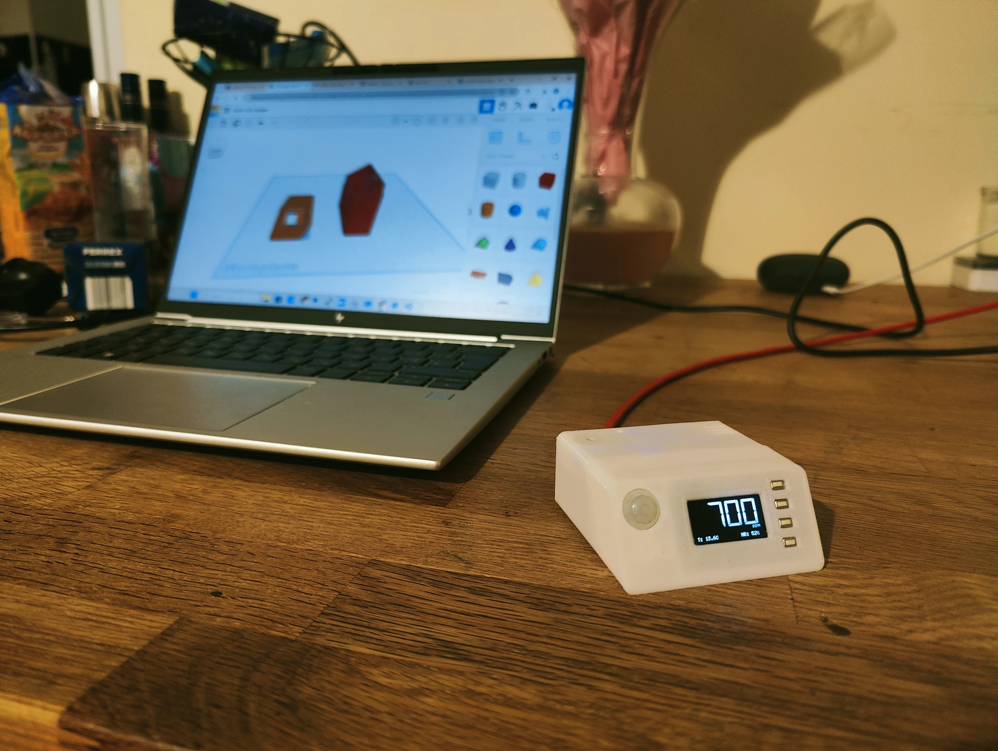
- Real-time OLED data display: Shows CO2 levels, temperature, and relative humidity on the screen.
- On-screen menu and hardware buttons: Allows easy navigation and adjustment of settings.
- Home Assistant integration: Works seamlessly via MQTT for smart home automation.
- Mobile app compatibility: Connects to the Sensirion MyAmbience app via Bluetooth.
- Web interface: Provides configuration options through a web-based UI.
- LED indicators: Two LEDs (yellow and red) provide visual alerts for elevated CO2 levels.
- Buzzer: Emits a sound alert for critical (red) CO2 levels.
- PIR sensor integration: Automatically turns the screen on and off based on proximity, extending screen life and saving energy.
- Firmware updates: Enables easy updates to keep the gadget current.
Components List

If you plan to print and use my version of the enclosure, it’s designed specifically for the components listed below. I’ve included links to where you can order them. So you will need the following:
- CO2 Sensor
(AliExpress affiliate link)
The most expensive component of the gadget is the CO2 sensor itself. I used the Sensirion SCD41 because it’s the most advanced model. You can opt for the more budget-friendly SCD40, but the price difference is only a few dollars or euros. - WeAct ESP32 Development Board Type-C
(AliExpress affiliate link)
A very convenient ESP32 board with plenty of GPIO pins. You can choose between the 4MB or 8MB Flash versions, but I recommend the 8MB version for future firmware updates in case the size increases. The price difference is only a few cents. - OLED Display with 4×4 Key I2C (SSD1315)
(AliExpress affiliate link)
Get a one color display for better compatibility with the fonts used. - AM312 PIR Motion Sensor
(AliExpress affiliate link)
Used to detect motion and control the screen activation. - Dupont Jumper Wires
(AliExpress affiliate link)
Get a set of 20 wires, each 10 cm long. You’ll need no more than 15 for this project. - Passive Buzzer (12MM)
(AliExpress affiliate link)
Used for audible CO2 level alerts. - Two 3mm LEDs (Yellow and Red)
Any standard 3mm LEDs will work. - Any 100-200 Ohm Resistor
Used to limit the current for the LEDs. I used 200 Ohm. - Soldering iron and basic soldering skills.
- Access to a 3D printer to print the enclosure.
Assembly of the Gadget:
1. 3D Printing the Enclosure
The 3D model of the enclosure can be downloaded from Tinkercad, Thingiverse or directly. The enclosure consists of two parts that snap together. Print each part separately. No supports are needed for printing, so ensure they are disabled. I used PETG filament, but other materials should work fine as well. Here are the recommended printing settings:
- Resolution: 0.2 mm (0.3 mm for the first layer)
- Infill: 20%
- Supports: Off
- Flow: 100%
- Initial Layer Flow: 115% (to make the first layer denser and reduce the risk of gaps)
- Adhesion Type: Skirt or Brim (6–8 mm, depending on the filament and your print bed adhesion).
2. Preparing the ESP32 and CO2 Sensor

- ESP32: Since the pin headers are not soldered on the ESP32, solder them so they face upwards, on the same side as the electronic components.
- CO2 Sensor: Use 90-degree angled pin headers for easier connections. If unavailable, solder standard pin headers so the pins face downward, opposite the sensor side.
3. Connecting the OLED Screen and CO2 Sensor via I2C
Both the OLED screen and CO2 sensor use the I2C protocol, so they can be connected in parallel to the same ESP32 pins:
- VDD (VCC) -> Any 3.3V pin on the ESP32
- GND -> Any GND pin on the ESP32
- SDA -> GPIO 21 on the ESP32
- SCL -> GPIO 22 on the ESP32


Parallel connection method:
I used a 4-pin female header with Dupont jumper wires to create a splitter. Strip the insulation at the center of each wire and solder them to the 4-pin header. Insulate the solder points with heat shrink tubing to prevent short circuits. The 4-pin header connects to the screen, while the Dupont wires connect to the ESP32 and CO2 sensor.
4. Connecting the Screen Buttons
Currently, only two buttons are used for the on-screen menu. Connect them using Dupont wires:
- K1 -> GPIO 15
- K2 -> GPIO 0
5. Connecting the PIR Sensor
- GND -> Any GND pin on the ESP32
- VCC -> Any 3.3V pin on the ESP32
- DATA -> GPIO 14
6. Connecting the LEDs
Both LED negative terminals (GND) should be connected together and linked to the ESP32 GND through a 100–200 Ohm resistor to limit current. Although direct connection without a resistor may work, the resistor is more reliable. Since the PIR sensor is close to the LEDs, you can solder the resistor to its GND terminal.


- Yellow LED -> GPIO 32
- Red LED -> GPIO 33
7. Connecting the Buzzer
- GND (-) -> Any GND pin on the ESP32
- VCC (+) -> GPIO 2
8. Flashing the Firmware
Before assembling the gadget into enclosure, test the components and connections by flashing the ESP32 firmware. We can do it directly from the browser using the web flasher tool below!

- Connect the ESP32 to your computer via a USB data cable.
- Click Connect button below, and select the COM port from the list. (If multiple ports appear, unplug the ESP32 to identify which one disappears, then reconnect it.)
- Follow the on-screen instructions. Check the “Erase Device” checkbox and flash the firmware.
- Press and hold the Boot button on the ESP32 during the flashing process until it connects and begins. Once flashing is complete, configure the Wi-Fi network and password.
Web Flasher Tool
After a successful connection, the gadget’s web interface will be available at http://co2-gadget.local. If this hostname doesn’t work, find the IP address assigned to the gadget by your router and use it instead.
The firmware files and source code can be found in my GitHub fork at this link.
9. Installing Components in the Enclosure


Once you’ve tested the gadget, assemble it into the enclosure:
- Disconnect all wires from the components.
- Install the OLED screen: Insert the lower part first, then secure the top.
- Insert the CO2 sensor into the square slot on the upper-right side of the enclosure (near the slits), with the pins facing the screen.
- Place the buzzer in the left slot. Push gently using a flathead screwdriver if needed. Insert the buzzer with wires attached, as connecting them afterward is harder.
- Fit the PIR sensor and LEDs into the cover near the screen. Use a hot glue gun for additional stability. Note: The LED holes are not through-holes. If using white or translucent plastic, light will shine through. For black plastic, you might need to drill through the holes.
- Insert the ESP32 with wires connected. First, slot the far end into the grooves near the wall, then press the near end down until it clicks into place.
- Reconnect the components to the ESP32, arranging the wires compactly above it.
- Snap the two enclosure parts together.
Your CO2 gadget is now assembled and ready to use!
Initial Setup
Calibrating the CO2 Sensor
To calibrate the sensor, take the gadget outside for fresh air. You can power it using a power bank. Since this type of sensor may give unstable readings in windy conditions or drafts, it’s best to place it in a box with open air access from the top. This minimizes the influence of drafts.
Wait until the sensor readings stabilize. Once stable, calibrate the sensor through the web interface or the on-screen menu. The outdoor CO2 level is typically around 400 ppm, but it can range from 600–900 ppm in urban areas. I use the default calibration value of 415 ppm.
In addition to CO2 levels, you may also need to calibrate the temperature readings. For example, my sensor showed significantly higher temperatures (8–10°C above actual). Use a reliable thermometer next to the sensor to check the actual temperature, and adjust the “Temperature Offset” value in the settings. This offset will be subtracted from the sensor’s readings. It can take up to few minutes to apply the offset by the sensor firmware.
Connecting to Home Assistant
To integrate the gadget with Home Assistant:
- Activate MQTT support in the web interface settings.
- Enter the MQTT broker address and credentials (If you can’t change MQTT password because it is blocked – add a “?relaxedSecurity” parameter to the end of the web page interface url).
- Once configured, the gadget should appear in Home Assistant under devices.
Mobile App
Sensirion sensors are compatible with the Sensirion MyAmbience mobile app via Bluetooth.
- Android: Google Play Store link
- iOS: App Store link
Install the app and ensure BLE (Bluetooth Low Energy) is enabled in the gadget’s settings. The app will automatically detect and connect to the sensor, making it very convenient to monitor the data.
Stay Updated
If you enjoyed this project and guide, follow us on social media (links in the website footer) to stay updated on similar DIY projects in the future.

I’ve got this built and it’s up and going with the firmware from the main page. How do I install your firmware? Thanks!
Hey, do you see a web flasher tool with a blue button “Connect” in the paragraph No8? If you don’t see it – try another browser, Chrome should work.
And that did it. Was in a different browser for your page only. Figures. Thanks much, went together pretty well. Tomorrow it goes in the case. Any idea why it says disabled for the MQTT User Password?
Not sure why the MQTT and Wi-Fi password input fields sometimes get disabled, will try to investigate someday. However, if you access the captive portal, you can change them there.
To enter the captive portal mode:
Thanks again, that seems to have fixed the PW issue. Now to continue to work on MQTT. I appreciate all the help. Great guide. Thank you.
Found easier way, just add “relaxedSecurity” param to the end of URL (eg. http://co2-gadget.local/preferences.html?relaxedSecurity). This will unlock both WiFi and MQTT password fields.
Здравствуйте. Может быть поможете разобраться, я ни разу не программист, но очень заинтересовался проектом CO2 Gadget. Собирал на e-ink+SCD41. Закачал прошивку браузером сразу в плату, запустил, гуд. Однако на сайте выложена прошивка обычная, не low power, и гаджет садится меньше чем за сутки.
Автор свой проект забросил, не появляется на гитхабе с лета прошлого года, по форку нашёл ваш репозитарий, почитал, вспомнил что видел картинку на хабре и решил написать, но там не получилось
Проблема в том, что не получается скомпилировать – сыпет ошибками. Установил vs code+Platformio, пытаюсь разобраться и никак.
Не получается скомпилировать ни вашу версию, ни первоначальную 0.14.006, ни low power.
Может быть подскажете конфигурацию настроек, какие расширения нужно дополнительно поставить Буду очень благодарен.
Здравствуйте, к сожалению нет времени разбираться почему у вас не компилируется. Дополнительно вроде ничего не ставил, версию для e-ink с батарейкой я даже не пытался компилировать, использовал только OLED. Вполне возможно вышли какие-то обновления и что-то теперь не работает как раньше. Могу разве что посоветовать обратиться к ChatGPT, мне помогал решать похожие проблемы лучше чем кто-то из комментариев 😉
Thank you for this amazing tutorial!
I am planning to build this project, and thinking of adding a BME280 for air pressure data as well.
However, I am not able to build the code from the github repo.
Is there any secrect trick or should `pio run` do it already?
Thank you!
Hi, try:
pio run -e esp32dev_OLED
If it is not enough you might also need to call:
.\webserver\MinifyCompressAllFiles.ps1
pio run -e esp32dev_OLED -t buildfs
pio run –target uploadfs
pio run –target upload
The idea of adding a BME280 should work. You can then use it to obtain more accurate temperature and humidity readings. The CO₂ sensor also provides these values, but they may not be very precise and often require offset calibration.